


MIRTEC MV-3 AOI SMT LINE AOI 2D Automated Optical Inspection System AOI Equipment AOI Machine For SMT Machine Line SMT Assembly Line
Whatsapp:+8613728632793, skype:Joaquin Xie,wechat:Joaquin15
Whatsapp:+8613424013606,skype:sensenhenhao,wechat:JoyLY0322 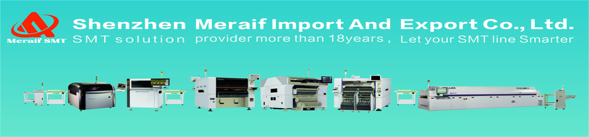
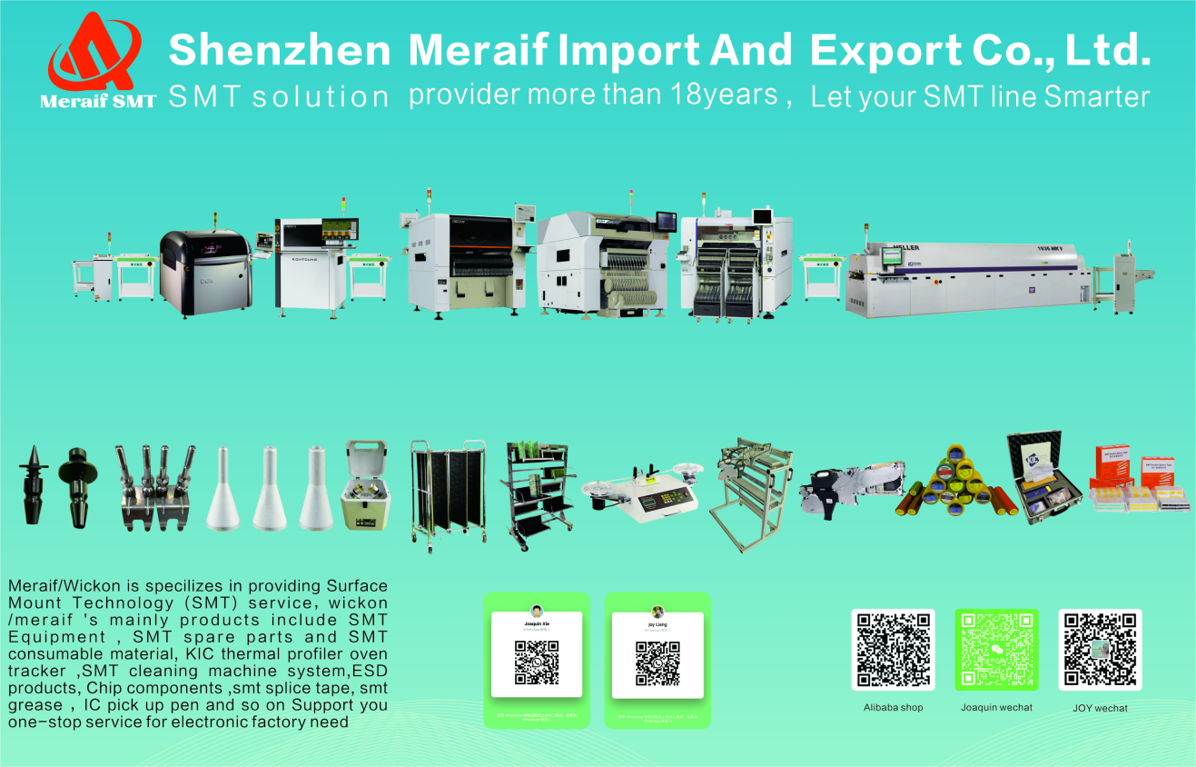
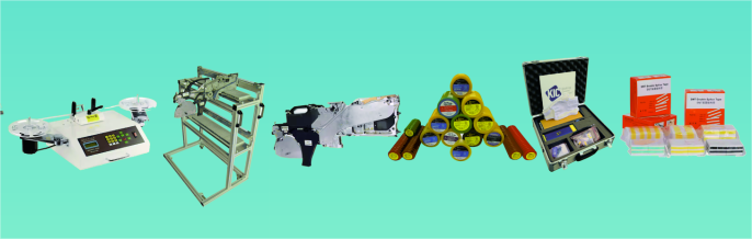
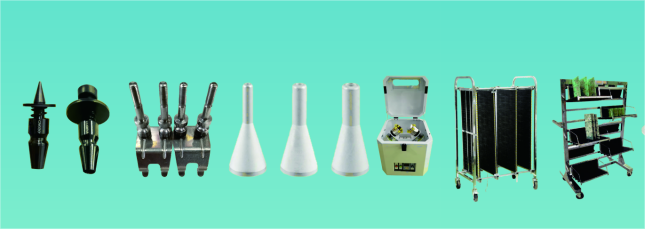
WE are smt support provider for smt machine parts and equipment .such as feeder,nozzle , feeder storage cart smt reel rack , smt grease , solder paste mixer, smd counter, KIC thermal profiler,smt tape and so on .
Also can support some original parts of machine repair.
Successful Experience:
1. We Have Been Helping Customers To Build a Lot of New Factories Around the World.Meraif's Customer In 35 Countries Around the World
2. Training More Than 500 Experts and Technician for Customers.
3. Became the Most Reliable Chinese Partner for You.
For SMT Factory Setup, We Can Do for You:
1. We Provide Full SMT Solution for You
2. We Provide Core Technology With Our Equipments
3. We Provide The Most Professional Tech Service
4. We Have Wealthy Experience on SMT Factory Setup
MIRTEC MV-3 AOI SMT LINE AOI Technical Parameters:
MODEL
MV-3L
MV-3U
Machine Dimensions
975(W)x1200(D)x595 mm(H)
1185(W)x1455(D)x610 mm (H)
Inspection Area
50x50~450x400 mm
50x50~660x510 mm
Weight
110 Kg
160 Kg
FOV/Resolution
2.0 Mega Pixel Camera System
Option 1
FOV.29.1×21.8 mm,Resolution:18.2 μm/pixel
Option 2
FOV:21.5×16.1 mm,Resolution:13.4 μm/pixel
Option 3
FOV:15.7×11.8 mm,Resolution:9.8 μm/pixel
5.0 Mega Pixel Camera System
Option 1
FOV.44,7×37,4 mm,Resolution:18.2 μm/pixel
Option 2
FOV.32,9×27,5 mm,Resolution:13.4 μm/pixel
Option 3
FOV:24,0×20,1 mm,Resolution:9.8 μm/pixel
2.0 Mega Pixel Camera System
Option 1
29 cm²/sec. (0,22 sec/frame)
Option 2
16 cm²/sec. (0,22 secframe)
Option 3
8 cm²/sec. (0,22 sec/frame)
5.0 Mega Pixel Camera System
Option 1
60 cm²/sec. (0,28 sec./frame)
Option 2
32 cm²/sec. (0,28 sec/frame)
Option 3
17 cm²/sec. (0,28 sec/frame)
Smallest Component Inspection
Option 1
0,4 pitch IC,0201 Chip
Option 2
0,3 pitch IC,01005 Chip
Option 3
0,3 pitch IC,01005 Chip
Inspection Item
Options
Top Down Camera
2.0 Mega (1600×1200 Pixels)
5.0 Mega (2456×2058 Pixels)
Side Viewer Camera
SideViewerB:2.0 Mega (1600x1200 Pixels)/4 set
SideViewerB:5.0 Mega(2,592x1,944 Pixels)/4 set
Lighting System
3D-Beam Laser Resolution/accuracy
Z-Height Repeating Measurement Accuracy:±20 μm(Resolution:15 μm/point)
PC
IntelR CoreTM 2 Duo,19"LCD Monitor,Windows XP Professional
Power Requirements
Single Phase AC 85~264V,50/60Hz
Environment
Temperature:10-40°C.,Humidity:30-80%RH
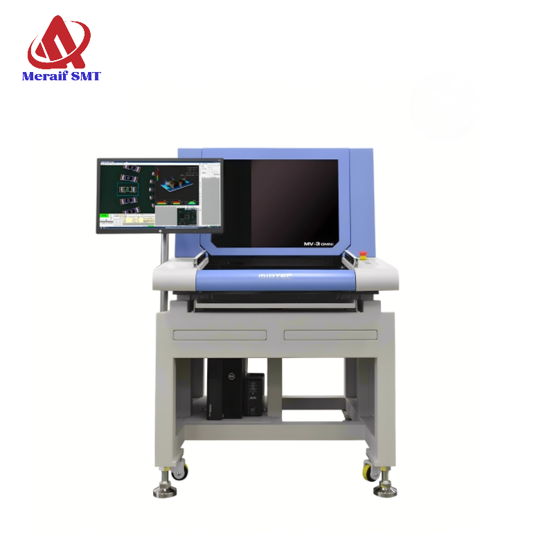
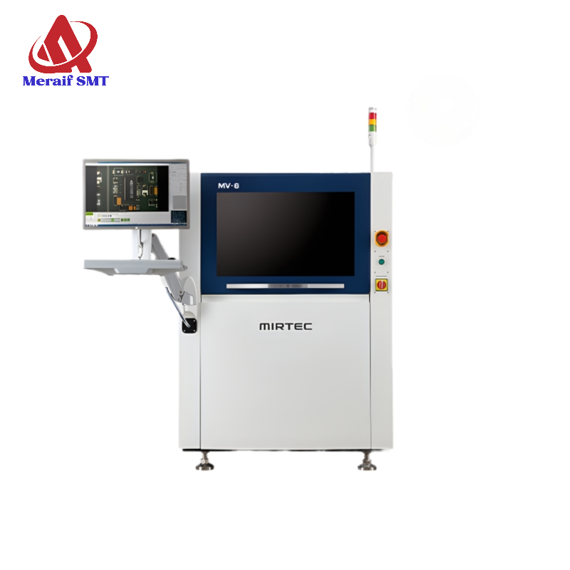
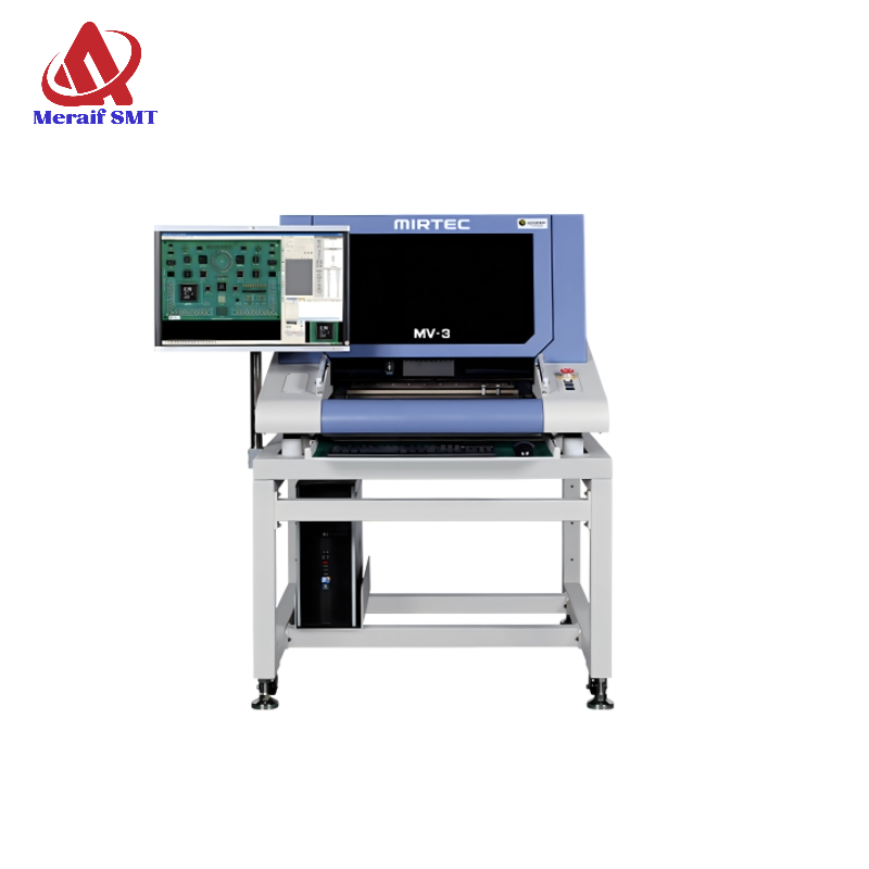
MIRTEC MV-3 AOI SMT LINE AOI Details:
The MV-3 Desktop AOI Systems are designed to automatically inspect for manufacturing defects both pre and post reflow. These systems offer superior fault coverage and will detect defects such as component presence/absence, polarity, miss alignment, insufficient solder, solder bridging, etc.
The system software is very powerful yet extremely simple to use. The standard SPC software package promotes continuous process improvement by allowing the user to track and eliminate defects on inspected assemblies.
1.FIVE Camera Desktop AOI System
2.TEN MEGA PIXEL Digital Color Camera technology
3.Precision TELECENTRIC Compound Lens Design
4.9.8 Micron / Pixel Resolution
5.Extremely Simple Programming and Operation
6.Unsurpassed Defect Detection
MIRTEC MV-3 AOI SMT LINE AOI Picture Show:


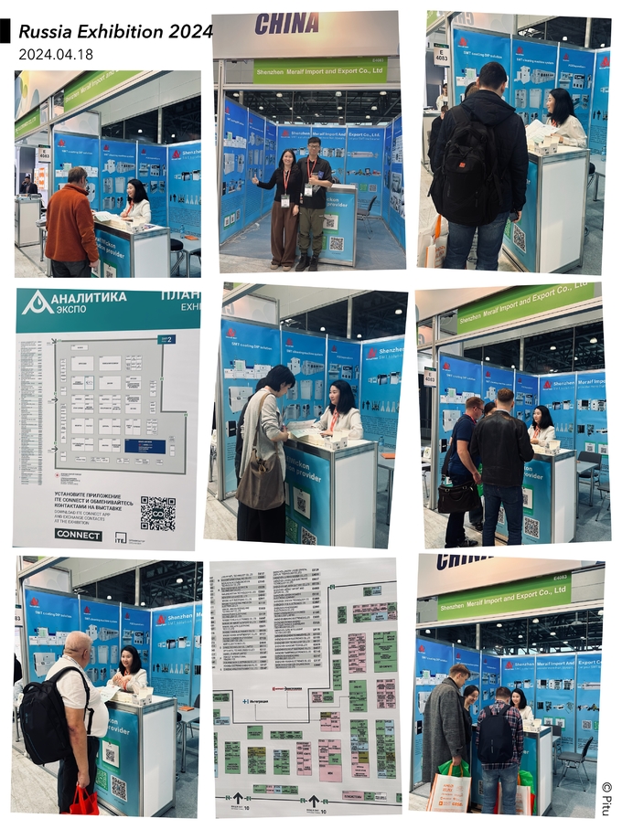
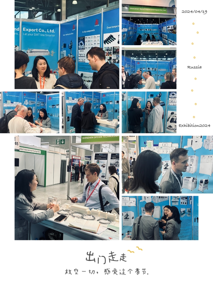
EXHIBITION:
SMT LINE:

EXHIBITION:
SMT LINE: